Dispenser Functions
Fluid metering device, regardless of type, is designed to provide two important functions in the mechanical refrigeration system. First, it allows the liquid refrigerant flow into the evaporator in the amount that corresponds to the rate at which the evaporator liquid refrigerant boils into steam. Secondly, it provides a pressure drop, separating the upper part of a system with the low side. This differential pressure allows the refrigerant in the evaporator boil at a low enough temperature to absorb heat into the system from the area or substance in cooling. It also allows the refrigerant in the condenser condense at a temperature high enough to reject heat from outdoor air.
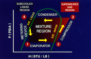
In the modules entitled Compressors, Condensers, Evaporators, we showed how the functions of each of these components look like when plotted on the P-H schema normal version (peak load) conditions. Here we used the same approach for the metering device.
As the refrigerant leaves the condenser, he entered the dispenser in point 4, as high pressure, high temperature, supercooled liquid.
Ten to fifteen degrees hypothermia is typical. He comes from the metering device, point 1, and low pressure, low temperature mixture of saturated liquid and vapor. As the refrigerant passes through the dispenser, he falls rapidly pressure, as shown in paragraphs 4 and 1. Unlike the refrigerant's passage through the compressor, condenser, evaporator, there is no change in enthalpy of the refrigerant as it moves through the dispenser. Straight vertical line connecting points 4 and 1 in the diagram falls on the same enthalpy line. This is because, unlike other components, the refrigerant flow through the dispenser almost instantly. There is so little time heat to be exchanged between the refrigerant in the metering device and the air surrounding device that can be ignored. For all practical purposes, we could say that the meter is purely a pressure drop of the device. Changing the saturation temperature of the refrigerant is the result of a pressure drop.
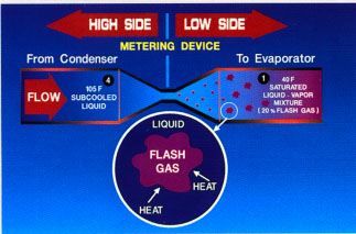
Refrigerant changes from supercooled liquids, saturated liquid-vapor mixture from the pressure and the saturation temperature drop caused by a metering unit. The saturation temperature on the high Bank of the metering device is determined by the pressure in the condenser, while, on the low side, it is determined by the pressure in the evaporator. To 105F liquid refrigerant in point 4 to fall by 40F saturation temperature at the point 1, the heat must be removed from the fluid in point 4. With the measurement process and does not show the change of enthalpy, heat has not been rejected out of refrigerant. Instead, some of the heat in the refrigerant transformed from a sense of latent heat.
Here's how it works: Some of the liquid refrigerant boils into steam at a temperature of saturation and becomes a flash strip. Quite sensible heat is rejected liquid refrigerant in the process of creating flash refrigerant gas and falls to the saturation temperature, which corresponds to the pressure in the evaporator. Similarly, enough latent heat is absorbed by the refrigerant in the production of flash gas for the production of similar drop the saturation temperature. Sensible heat loss of fluids, accompanied by the latent heat of strengthening an equal amount of steam. At evaporator inlet, a mixture of 80% of saturated liquid and 20% saturated vapour (flash gas) about normal for comfort cooling.
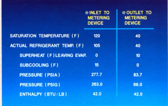
Here are some typical changes of the metering device will cause the R-22 in the system of air-cooled condenser. These data assumes an outside temperature of 95F...
|


