Thermostatic Expansion Vaive Design
Thermostatic valves are normally used on multi-evaporator systems. However, the low on the side of the float can also be used on multiple systems. Several system using thermostatic valves provide different temperatures in different offices. This valve is also widely used in air conditioning systems.
The correct sensor element should be selected for each installation. The correct size of the valve are also necessary. Thermostatic expansion valve has a brass casing, in which the liquid line and evaporator lines are connected. Needle and place inside the body. Needle joined flexible metal bellows or diaphragm. Bellows moves with the rod, comiected at the other end of sealed bellows or diaphragm (a battery). It acceded to the sensing bulb through the capillary tube. Fig. 5-13 shows the refrigerant behavior in a sensitive element.
Every manufacturer has a code to identify the fluid that accusations of the sensing element. Some use characters and use other colors, and numbers. Some valves are marked quantity of refrigerant.
Some valves are designed for use with refrigerant R-12, colored yellow.
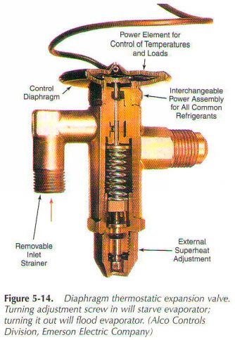
The valve is sealed to prevent the penetration of moisture in it. Strainer (screen) is located between the liquid line connection and holes. This will help dirt from the needle and the seat. Cm. Fig. 5-14.
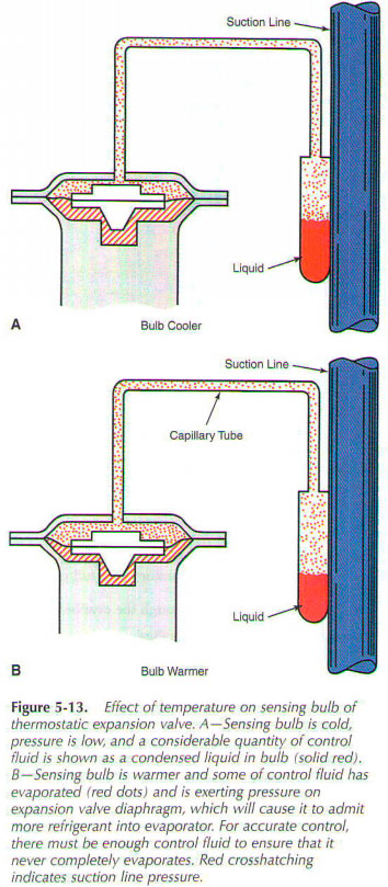
Figure 5-15A illustrates the thermostatic expansion valve with integral check valve. Non-return valve will not let the refrigerant flowГў system back through TEV. This type of thermostatic expansion valve is used in hot gas defrost applications. Figure 5-15 - exploded view thermostatic expansion valve.
Figure 5-16 illustrates the large capacity of flat seat valve. Filter drier must be placed in the liquid line immediately before the thermostatic expansion valve. Fig. 5-17 shows the incision type of membrane type TEV. Fig. 5-18 shows the context of the ball valve.
Another type of thermostatic expansion valve is shown in Fig. 5-19. Single diaphragm valve is designed to service the AG-conditioning systems. It is equipped with a venting valve for rapid pressure balance (RPB). Bleeding mechanism works only when the compressor is not running. When the compressor is running, secondary bleeding port is closed. Then the valve is operating in normal mode. Rods bear aperture action on the needle. The liquid at the inlet to the left; consoles to connect the evaporator on the right.
 .. ..
|

 ..
..