Refrigerator Troubleshooting. The Muff disk
Instead of applying the flywheel disk options, compressors, can be designed for direct communication. The coupling on small compressors can be rigid flange type. Large compressors will have a more complex elastic coupling, like the one shown in Fig. 95, consisting of a flange Assembly, the center of the ring Assembly, a number of forged links, and long and short bolts with lock nuts and washers. 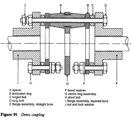
Assembling and adjustment Whenever couplings have the right alignment is essential to prevent excessive stress on the compressor, electric motor shaft and bearings, and to eliminate vibration during operation, which is often at high speeds. In case of necessity to change the engine or the compressor, it is important to note the location of bolts, washers, forged links and nuts during disassembly, because they must be replaced in the same order. The most accurate method of combining the coupling with the help of the sensor level indicator, but this can be accomplished with straight edge and caliper.
Both methods will be considered in turn. It is desirable to align the connection with the tolerances specified by the manufacturer. Level indicator sensor Test for angular misalignment 1 set the indicator on the left hand flange, as shown in Fig. 96, with the stem on the face of the right hand of the flange.
2 Turn the equipment, the concept of maximum and minimum indicator.
3 Move the equipment necessary to reduce the total indicator reading 0.0508 mm (0.002 in) or less for each millimetres (inch) diameter rod indicator. 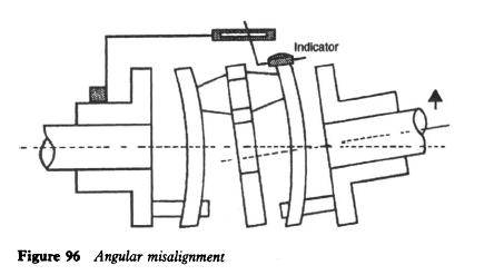
Test for parallel misalignment 1 Set the indicator on the outer surface of the flange as shown in Fig. 97.
2 Turn the equipment, noting the maximum and minimum readings. 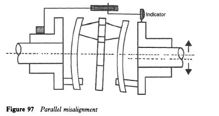
3-Moving equipment as necessary to reduce the indications of the indicator to a minimum, trying not to disturb the settings in step 1.
4 the coupling should be rotated several full turns, to make sure that axis creep in connected shafts is measured.
5 Tighten all bolts. Check the tightness after a few hours of work. Calipers and straight edge 1 Place the straight edge of the wheel flanges at the top and sides (Fig. 98). The coupling alignment, straight edge should rest in full contact on the wheel flange.
2 make sure measurements inside calipers at least four points on the circumference of the flanges. If these dimensions are within 0.39 mm (6 and 4 inches from each other, the alignment is satisfactory. Refer to the manufacturer's instructions (if available).
3 Moving equipment and repeat steps 1 and 2, if necessary.
4 Tighten all bolts. Check the tightness after a few hours of work. 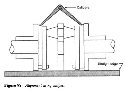
Appearance Couplings in the correct alignment, as laminated rings to be the ideal plane at right angles to the centre line of the shaft. When the machine is running at full speed, as laminated rings should very clearly defined appearance when viewed from above and to one side. They should have blurred appearance, the clutch should be rebuilt. Installation In the course of the coupling alignment you may need to increase the level of shaft coincides with the shaft of the compressor. This can be achieved by placing membranes (Fig. 99) under the motor; strip hiding the location of the engine mounting bolts. It will then be necessary to conduct a parallel alignment test a few hours after the equipment work in the case of strips have bedded down, thus providing the clutch out of alignment. When the clutch was correctly aligned and worked satisfactorily, holes should be drilled motor and mounting base. It can either be used to get the bolt or left untapped for the insertion of a pin. Protection will ensure that no angular displacement driver shaft possible. 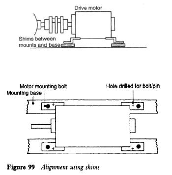
..
|
