Steam Jet Refrigeration Systems
The steam jet cooling water can be used as a refrigerant. Like air, it's perfectly safe. These systems have been successfully used for cooling in the early years of this century. At low temperatures saturation pressure low (0.008129 bar 4BC) and specific volumes of high (157.3 m3/kg / 4BC). The temperature that can be achieved with the use of water as a refrigerant are not low enough for the majority of refrigeration applications, but are in the range that can meet the air conditioning, refrigeration and cooling requirements. In addition, these systems are used in some chemical production processes, for example. solid paraffins lubricants. Please note that the steam temperature refrigeration systems are not used at temperatures below 5VC is required. The main advantage of this system is the use of mainly low-grade energy and relatively small amounts of shaft work.
The steam refrigeration systems use steam ejectors for reduction of pressure in a tank containing water returning from the chilled water system. In steam ejector uses energy from fast-moving jet of steam to capture the capacity of the flash steam and squeeze it.
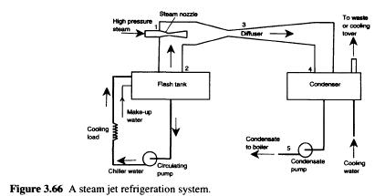
Flashing of the water in the tank reduces the temperature of the liquid. Figure 3.66 presents agreement in principle on the steam refrigeration cooling water systems. The system shows high pressure steam expands as it flows through the nozzle 1. Extension causes a drop in pressure and a huge increase in speed. Due to the high velocity, flash vapours from the tank 2, absorbed quickly moving and steam mixture enters the diffuser 3. The speed gradually decreases in the cone but steam pressure in the condenser 4 is 5-10 times more than at the inlet of the diffuser (e.g. from 0.01 0.07 bar bar).
This pressure value corresponds to the temperature of condensation 40VC. This means that the mixture of high-pressure steam and flash evaporation can be liquefied at the condenser. Latent heat of condensation is passed to the condenser water, which can be 25 InC. condensate 5 pumped back to the boiler, from which he can again turns to high-pressure steam. Evaporation relatively small amount of water in capacity of the flash (flash or cooler) reduces the temperature of the body of water. Chilled water is pumped as a cooling carrier cooling load, the heat exchanger. 
Ejector was invented by Sir Charles Parsons around 1901 to remove air from the steam engine capacitors. About 1910, ejector was used Maurice LeBlanc the steam ejector system cooling It experienced a wave of popularity in the early 1930s to the air conditioning systems in large buildings. Steam ejector refrigeration cycles were later driven systems using mechanical compressors. Since then, development and refinement of ducted cooling system were almost at a standstill as the main efforts were focused on improving the vapour compression cycles (Aphornratana et al., 2001). In addition, another typical gas-driven ejector is shown schematically in Fig. 3.67a. High pressure liquid primary (P) is adjudged to be in the main nozzles, through which it expands to produce low-pressure region at the output of the aircraft (1). High-speed main stream attracts and captivates the secondary fluid (S) in the mixing chamber. Combined flows are completely mixed at the end of the mixing chamber (2) and velocity of the flow is supersonic. Normal shock wave, then made in the mixing chamber throat (3), creating the effect of the compression and speed of the flow is reduced to a subsonic value. Further compression of liquid is achieved as a mixed stream flows through the subsonic diffuser section (b).

Fig. 3.67b is a schematic diagram of the ejector refrigeration cycle. It is seen that the boiler, ejector pump is used to replace mechanical compressor conventional system. High pressure and high temperature of the refrigerant vapor developed in a boiler to obtain primary environment for the ejector. Ejector draws of refrigerant vapour at the outlet of the evaporator as additional. This causes the refrigerant evaporates at low pressure and produce a useful cooling. Ejector exhaust vapour refrigerant in the condenser where it is liquefied. The liquid refrigerant stored in the capacitor is returned to the boiler by means of the pump and the rest is expanding with the throttle to the evaporator, thus completing the cycle. As a labour input required to circulate the fluid, usually less than 1 % of the heat supplied by boiler KS can be defined as the ratio of the evaporator cooling load on a supply of heat to the boiler as follows: 
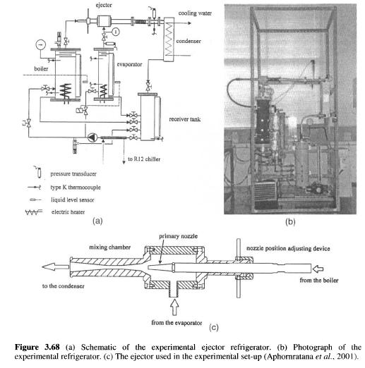
Recently, Aphornratana et al. (2001) have developed a new jet ejector cooling systems using R-ll as a refrigerant, as shown in Fig. 3.68. All the capacity of the system were constructed of galvanized steel. The boiler was designed to be electrically heated, two 4 kW electric heaters are located on the lower end. At its upper end, three partitions were welded to the vessel to prevent liquid drops is carried out with refrigerant vapor. Evaporator design was like a boiler. One 3 kW electric air heater was used to simulate the cooling load. Water cooled heat exchanger was used as a condenser. Cooling water was supplied to 32VC. boiler was covered with a 40 mm, thickness of glass wool with aluminum foil. Evaporator was covered with a 30 mm thickness neoprene foam. Piston pump is used for the circulation of the refrigerant from the receiving tank of boiler and the evaporator. Pump, driven by a variable speed 1/4 HP motor. One drawback to using a diaphragm pump cavitation liquid refrigerant in the suction line of a pressure drop through the inlet check valve. Therefore, small hmm was used to sub-cool the liquid R-11 before entering the pump. Fig. 3.68c shows a detailed scheme of the experimental ejector. The nozzle was mounted on a threaded shaft, which allowed the position of the nozzle to be adjusted. Two different camera confusion with the throat diameter of 8 mm are used in the mixing chamber, no.l, mixing section is in constant area of the duct: in the mixing chamber № 2, mixing section convergent duct. Aphornratana et al.’s experiments have shown that the ejector-cooling system with the help of R-11 was practically useful and can provide an acceptable level of performance. It can provide cooling temperature-5VC. cooling capacity ranged from 500 to1700 W (COP) in the range from 0.1 and 0.25. 
..
|
