Screw Compressors
Screw compressors are often used in large capacity systems in the range from 20 to 300 tons. They are open, outward-compressors, or hermetic internally-compressors. Open screw compressors the most often used with ammonia systems. Hermetic screw compressors are used halocarbons with refrigerants.
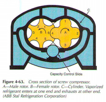
Screw compressor uses a pair of special screw rotor. These traps and compress the air, they rotate in exactly the machining of compressor cylinders. Fig. 4-63 illustrates the cross section of the screw compressor. Two rotors not in the same form. One male, the other female. Tyres rotor is driven by an electric motor. It has four blades. Female rotor, B, grid and managed by the rotor. He has six interlobe spaces. Cylinders, C, embodies both the rotor.

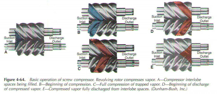
In the operation of refrigerant vapour is drawn as shown in Fig. 4-64. Consumption (low vapour pressure) is included in one end of the compressor and is reset (compressed steam) on the opposite end.
Male rotor rotates faster than the female of the rotor. (There are four tabs on the rotor and six women rotor.) Rotors have a spiral. They provide a continuous stream of actions and not pulsates with piston compressor. With this pumping action, there is very little vibration during the operation.

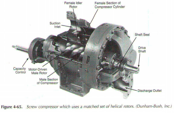
Fig. 4-65 illustrates cutaway view of external drive screw compressor. It is powered from an external electric motor that drives the drive shaft. As mentioned earlier, the motor drives the rotor. Two pairs of screw rotormale and female turn together. This action traps and compresses the refrigerant. Male rotor figure is the expansion of the shaft. Another rotor in turn, under the influence of the rotor. Control device installed outside the body regulates power to the unit.

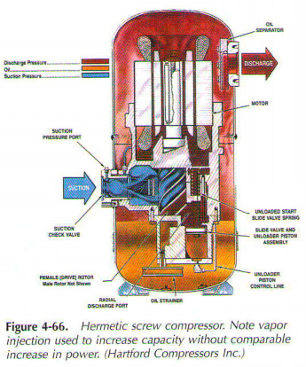
Hermetic screw compressor shown in Fig. 4-66. Its inlet is located at right angle to the rotors. Outlet-via the motor housing. It capacitv control device is mounted inside the housing. This ability to control the slide in the housing wall is used to vary productivity of the screw compressor. It provides a unique feature of the screw, his ability to control capacite through continuous unloading. This design provides fast, precise control of temperature in air-conditioned comfort. The pumping action of the compressor continuously, creating very little vibration during operation.

Fig. 4-67 illustrates 3600 rpm, one of the screw compressor. He uses one of the main rotor, which will be tied to the two diametrically opposite star gate rotors. The main rotor contains six grooves. It has direct roller bearings at shaft ends. Two management capacity slide valves one on each side, to help determine the capacity management. Fig. 4-68 is complete single screw compressor unit with microprocessor control system.

Many screw compressors work with oil injection. This seal the gap between the rotors and between the rotors and cylinder. It also helps the cooling compressor. The effectiveness of these compressors is quite high...
|


